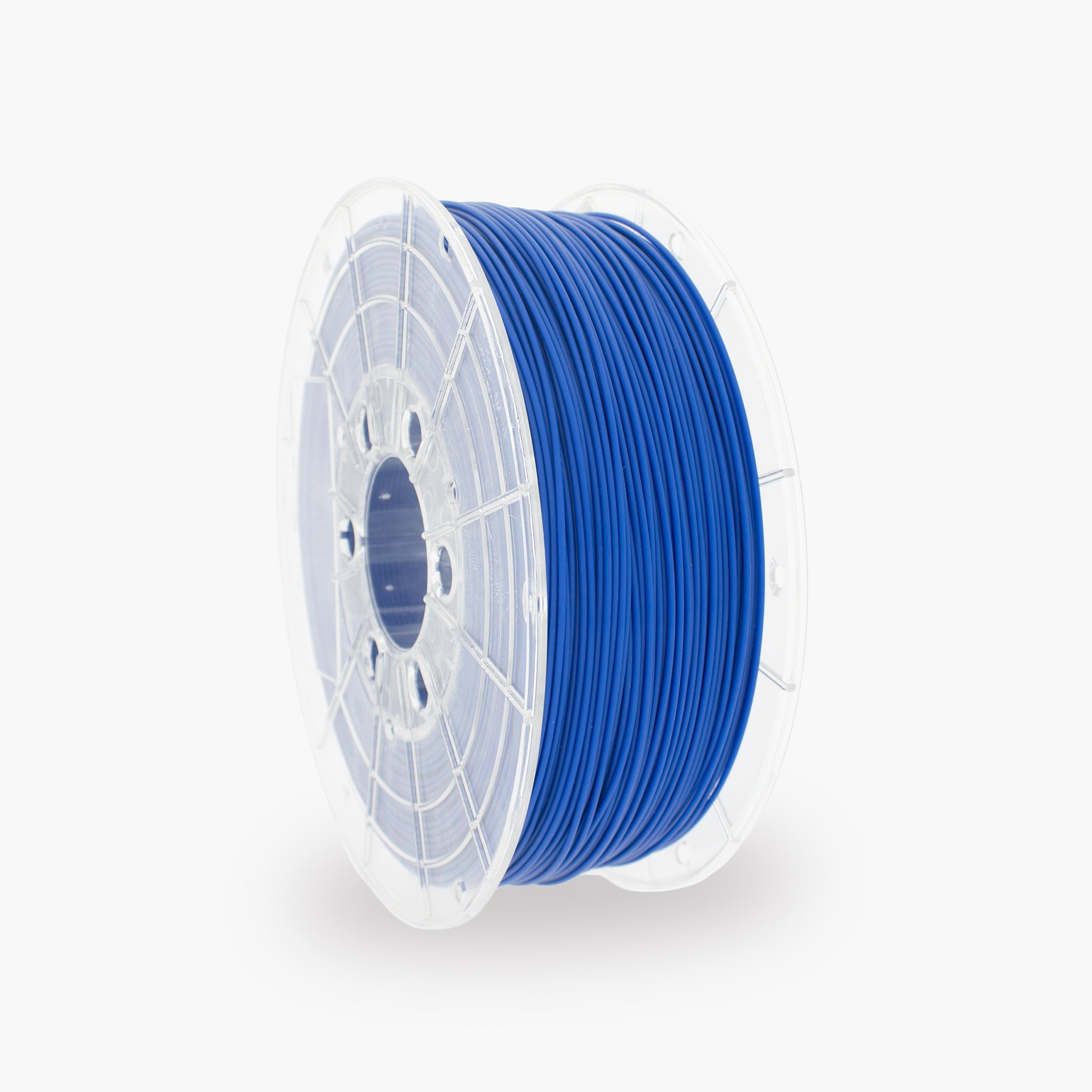

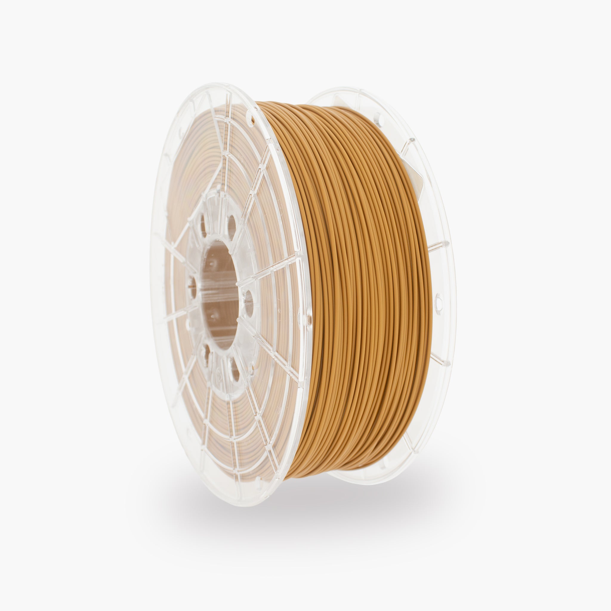
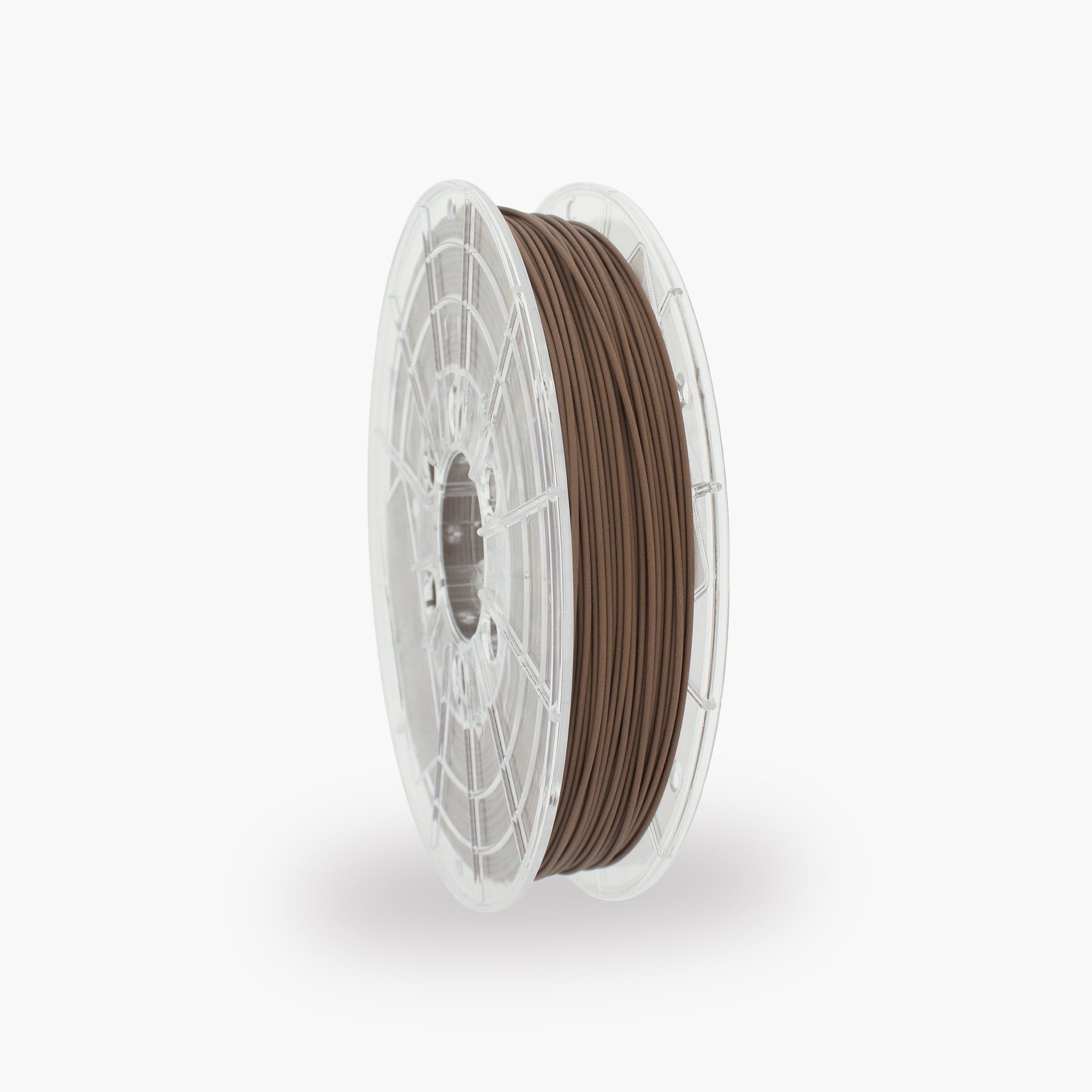
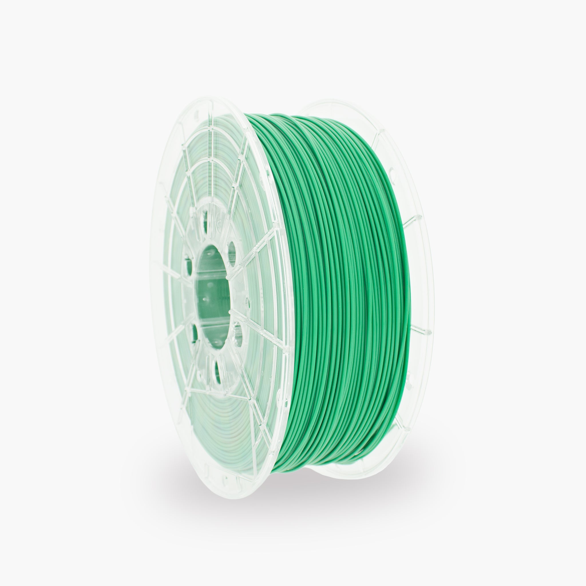



How do you print with TM3D PC?
Polycarbonate, also known as PC, is a strong and heat-resistant technical filament for heavy-duty and functional parts. In this guide, you will find recommended settings, tips for reducing warping, and solutions to common PC printing problems.
The most important PC settings
Use these settings as a starting point. The ideal values may vary depending on the printer, hotend, nozzle, print bed, and PC variant.
What is polycarbonate?
A strong technical filament for parts that must withstand mechanical loads and higher temperatures.
PC stands for polycarbonate. The material is known for its high impact resistance, strength, and temperature resistance. PC is widely used for technical prototypes, machine parts, enclosures, and parts that need to be stronger and more heat-resistant than standard PLA or PETG.
Benefits of PC
- Very good impact resistance
- High mechanical strength
- Good temperature resistance
- Strong adhesion between print layers
- Suitable for functional parts
- Suitable for heavy-duty applications
Suitable applications
- Machine parts and structural components
- Technical enclosures
- Mounting brackets and holders
- Functional prototypes
- Parts around heat sources
- Impact-resistant protective covers
Recommended print settings for PC
Start with the values below and then adjust one setting at a time.
| Setting | Recommended value | Explanation |
|---|---|---|
| Nozzle temperature | 260–290 °C | Start around 270–280 °C and adjust the temperature based on the PC variant, print speed, and layer adhesion. |
| Print bed | 100–120 °C | A hot print bed helps limit shrinkage and prevents corners from coming loose during printing. |
| First layer | 15–30 mm/s | A slow first layer gives the material enough time to adhere properly to the print surface. |
| Other layers | 30–100 mm/s | The maximum speed depends on the hotend, nozzle, printing temperature, and the printer's volumetric capacity. |
| First-layer fan | 0% | Keep the fan off during the first layer for good adhesion. |
| Fan for other layers | 0–10% | Use as little cooling as possible. Limited cooling may only be needed for bridges and small details. |
| Print chamber | Enclosed and heated | A stable temperature around the model reduces warping and cracking between layers. |
| Nozzle | From 0.4 mm | A standard nozzle is suitable for unfilled PC. For a filled PC variant, use a wear-resistant nozzle. |
Which printer is suitable for PC?
Not every 3D printer can safely reach the temperatures required for polycarbonate.
Recommended printer features
- Hotend suitable for at least 280 °C
- Print bed suitable for at least 100 °C
- Enclosed print chamber
- Suitable technical print surface
- Reliable bed leveling
- Good temperature control
Check before printing
- The maximum hotend temperature
- The maximum print bed temperature
- Whether the hotend is fully metal
- Whether the build plate can withstand high temperatures
- Whether the printer has sufficient ventilation or exhaust
- Whether the spool can unwind freely and without obstruction
Preparing the printer
A stable temperature, good bed adhesion, and dry filament are essential when printing with PC.
How to achieve a good first layer
A reliable first layer prevents the PC print from coming loose or warping during printing.
You can recognize a good first layer by:
- The print lines connect neatly to one another
- The filament adheres across the entire surface
- The lines are evenly flattened
- No gaps appear between the lines
- The corners remain flat on the build plate
Check the following if adhesion is poor:
- Whether the print bed is clean and free of grease
- Whether the Z-offset is set correctly
- Whether the print bed is sufficiently warm
- Whether the first layer is printed slowly
- Whether the fan is turned off during the first layer
- Whether cold air is flowing past the printer
Why an enclosed print chamber is important
Polycarbonate can shrink significantly while cooling. An enclosed print chamber keeps the temperature around the model more stable.
Benefits of an enclosed printer
- Fewer temperature differences
- Lower risk of warping
- Better adhesion between the layers
- Lower risk of cracking in tall models
- More reliable printing of large parts
Avoid during printing:
- Opening doors and panels
- An open window next to the printer
- Air conditioning aimed at the printer
- Sudden temperature fluctuations
- Removing the hot print immediately
Useful slicer settings
These settings have a major impact on the part's strength, dimensional accuracy, print time, and reliability.
| Part | Starting value | Effect |
|---|---|---|
| Layer height | 0.20 mm | Good balance between quality, layer adhesion, and print speed with a 0.4 mm nozzle. |
| Wall lines | 3–5 | More wall lines make functional parts stronger and more robust. |
| Top and bottom layers | 5–7 | Creates closed and stronger top and bottom surfaces. |
| Infill | 20–35% | Suitable for most functional parts and technical prototypes. |
| Infill for heavily loaded parts | 35–60% | Use more infill when the part is subjected to heavy mechanical loads. |
| Brim | 8–15 mm | Increases bed adhesion and reduces the risk of corners lifting. |
| Fan | 0–10% | Use as little cooling as possible for normal layers. Extra cooling may be temporarily needed only for bridges. |
| Print speed | 30–100 mm/s | Start slowly and increase the speed only after layer adhesion and material flow are reliable. |
Adjusting the nozzle temperature
The optimal PC temperature depends on the variant used, the hotend, the print speed, and the desired layer adhesion.
Temperature may be too low
- Poor adhesion between the layers
- Rough or matte extrusion
- The extruder clicks or skips steps
- The part breaks between the layers
- The material comes out of the nozzle inconsistently
Temperature may be too high
- A lot of stringing or thin strands
- Weak overhangs and bridges
- Details are merging together
- Material leaks from the nozzle during travel moves
- The surface becomes unnecessarily glossy or soft
Solving common PC problems
Click a problem to view the possible causes and solutions.
The corners of the print are lifting
- Thoroughly clean the print bed and remove all grease.
- Use a brim of approximately 8 to 15 mm.
- Increase the print bed temperature.
- Turn off the fan or set it to a very low speed.
- Use a closed and preheated print chamber.
- Avoid cold air currents around the printer.
Cracks form between the layers
- Increase the nozzle temperature by 5–10 °C.
- Reduce the print speed.
- Turn off the fan.
- Increase the temperature in the print chamber.
- Keep the doors and panels closed during printing.
- Let the print cool slowly after printing.
The print does not adhere to the print bed
- Clean the print bed and remove all grease.
- Check the bed leveling and Z-offset.
- Reduce the speed of the first layer.
- Use a sufficiently high bed temperature.
- Use a suitable adhesion layer for PC.
- Turn off the fan during the first layer.
The extruder clicks or skips steps
- Check whether the nozzle is partially clogged.
- Slightly increase the nozzle temperature.
- Reduce the print speed or volumetric speed.
- Check the tension of the extruder gear.
- Check that the filament unwinds freely from the spool.
Many strings form between parts
- First check whether the filament is dry.
- Reduce the nozzle temperature in 5 °C increments.
- Calibrate the retraction settings.
- If necessary, increase the travel speed.
- Limit unnecessary movements across open spaces.
The surface is rough or contains small holes
- Dry the filament before continuing to print.
- Check whether the material crackles during printing.
- Calibrate the flow or extrusion multiplier.
- Reduce the print speed.
- Check the nozzle for contamination.
Overhangs and bridges sag
- Reduce the speed of bridges and overhangs.
- Slightly reduce the nozzle temperature.
- Use limited cooling temporarily only for bridges.
- Use support for heavy overhangs.
- If necessary, reduce the layer height.
The part warps while cooling
- Let the print cool in the closed printer.
- Do not open the print chamber immediately after printing.
- Remove the part only after the print bed has cooled.
- Avoid large temperature differences.
- For large parts, adjust the design or orientation.
The part dimensions are incorrect
- Take polycarbonate shrinkage into account.
- Calibrate the flow and check for over-extrusion.
- Check the dimensions of the 3D model.
- Use the slicer's compensation settings.
- First print a dimensionally accurate calibration model.
The part breaks between the layers
- Increase the nozzle temperature.
- Reduce the fan speed.
- Reduce the print speed.
- Increase the number of wall lines.
- Use dry filament.
- If possible, increase the temperature in the print chamber.
Designing PC parts for maximum strength
The geometry and print orientation influence strength at least as much as the material selected.
Recommended design choices
- Use rounded inside corners
- Use sufficient wall thickness
- Reinforce heavily loaded mounting points
- Add ribs to large flat sections
- Avoid sudden transitions in wall thickness
- Use multiple wall lines around screw holes
When considering print orientation, pay attention to:
- The direction of the mechanical load
- The weaker Z-direction between the layers
- The required support material
- The location of sharp corners
- The size of the contact surface
- The desired surface quality
Storing and drying PC
Polycarbonate is sensitive to moisture. Damp filament can cause stringing, bubbles, and severely reduced layer adhesion.
Storing PC properly
- Store the spool in an airtight bag or drybox
- Use sufficient active desiccant
- Store the filament in a dry place
- Do not leave the spool open unnecessarily long
- Close the packaging immediately after use
- Preferably print directly from a drybox
Signs of damp PC
- Crackling or popping sounds
- Bubbles in the extrusion
- Small holes in the print surface
- A lot of stringing between parts
- A rough or foamy surface
- Reduced adhesion between layers
Material properties of TM3D PC
The data below provides a general overview of the material.
| Material | Polycarbonate, abbreviated as PC |
|---|---|
| Filament diameter | Depending on the selected version |
| Key properties | Strong, impact-resistant, stiff, and resistant to higher temperatures |
| Recommended nozzle temperature | Approximately 260–290 °C, depending on the PC variant |
| Recommended print bed temperature | Approximately 100–120 °C |
| Recommended fan | 0–10% |
| Enclosed print chamber | Strongly recommended |
| Moisture sensitivity | High |
| Suitable nozzle | Standard nozzle for unfilled PC and a wear-resistant nozzle for filled PC variants |
| Use | Technical parts, machine components, housings, fasteners, and heat- and impact-resistant applications |
The exact properties and recommended settings may vary by product variant, colour, printer, and test method. For technical applications, always consult the current technical data sheet.
Safe printing with PC
When printing with polycarbonate, ensure a safe, well-ventilated, and suitable workspace.
- Ensure sufficient ventilation or suitable air extraction.
- Check that the printer is safely suitable for the set temperatures.
- Do not touch the hot nozzle or heated print bed.
- Do not leave a printer operating unattended unnecessarily.
- Keep the printer away from flammable materials.
- Do not automatically use printed parts for food contact, medical applications, or safety-critical applications.
- Refer to the safety data sheet for additional product information.
Frequently asked questions about PC
Can I print TM3D PC with a standard PC profile?
Yes. Use your printer's standard or Generic PC profile as a starting point. Then check that the nozzle temperature, bed temperature, and cooling match the recommended settings for the TM3D PC variant being used.
Do I need a closed printer for PC?
A closed printer is strongly recommended. A stable temperature around the model reduces warping and lowers the risk of cracking between the print layers.
Do I need to dry PC before printing?
PC is sensitive to moisture. When in doubt, it is advisable to dry the filament before use and feed it from a dry box or filament dryer during printing.
Why is my PC print warping?
Warping is caused by shrinkage and temperature differences. Use a heated print bed, a closed and preheated print chamber, a suitable adhesion layer, and a wide brim for larger models.
Can I print PC on an open printer?
Small parts may sometimes be successfully printed on an open printer under favorable conditions. For larger, dimension-critical, or heavily loaded parts, a closed print chamber is strongly recommended.
Which nozzle can I use?
For regular, unfilled PC, a standard brass or suitable metal nozzle can be used. For PC with carbon fiber, glass fiber, or other abrasive additives, a wear-resistant nozzle is required.
Why aren't the layers of my PC print adhering properly?
This may be caused by a nozzle temperature that is too low, excessive cooling, a cold print chamber, a print speed that is too high, or moist filament. Increase the temperature gradually and check how the filament is stored.
Is PC stronger than PLA and PETG?
PC generally offers greater impact resistance and temperature resistance than standard PLA and PETG. However, actual strength also depends heavily on print orientation, wall thickness, infill, layer adhesion, and design.
Can PC be used outdoors?
That depends on the specific PC variant and the duration of exposure to UV radiation and weather conditions. For long-term outdoor applications, ASA may often be a more suitable choice.
Why does the filament crackle during printing?
Crackling and small bubbles usually indicate moisture in the filament. Dry the spool according to the current technical data sheet and then store it airtight.
Ready to print strong technical parts with PC?
Discover TM3D PC filament for strong, impact-resistant, and heat-resistant 3D prints, technical prototypes, and functional applications.
View the PC filament